Hi,
Yesterday I published building instructions for a single leg of my holonomic robot Agilis. Here are the full instructions. These include the central frame and three sensor docks. Have fun with it.
Download the Building instructions

Hi,
Yesterday I published building instructions for a single leg of my holonomic robot Agilis. Here are the full instructions. These include the central frame and three sensor docks. Have fun with it.
Download the Building instructions
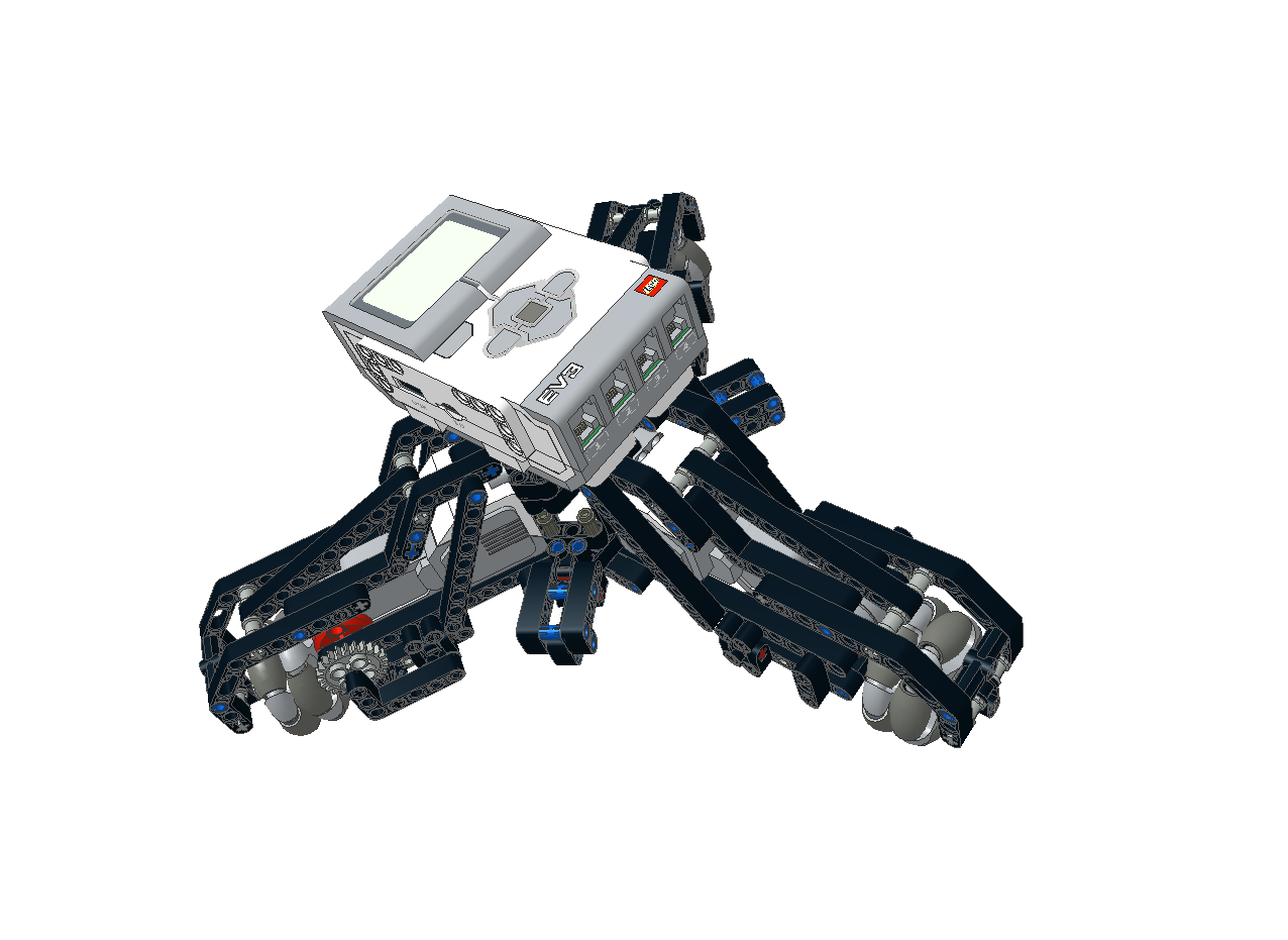
The large EV3 motor has a different form factor then the NXT motor. I had to redesign the legs of Agilis to make use of these new motors.

 The new design is smaller and much prettier to the eye. The smaller size and all the triangular shapes makes the leg very stable. The new leg can be fitted on the same triangular frame that was used for Agilis.
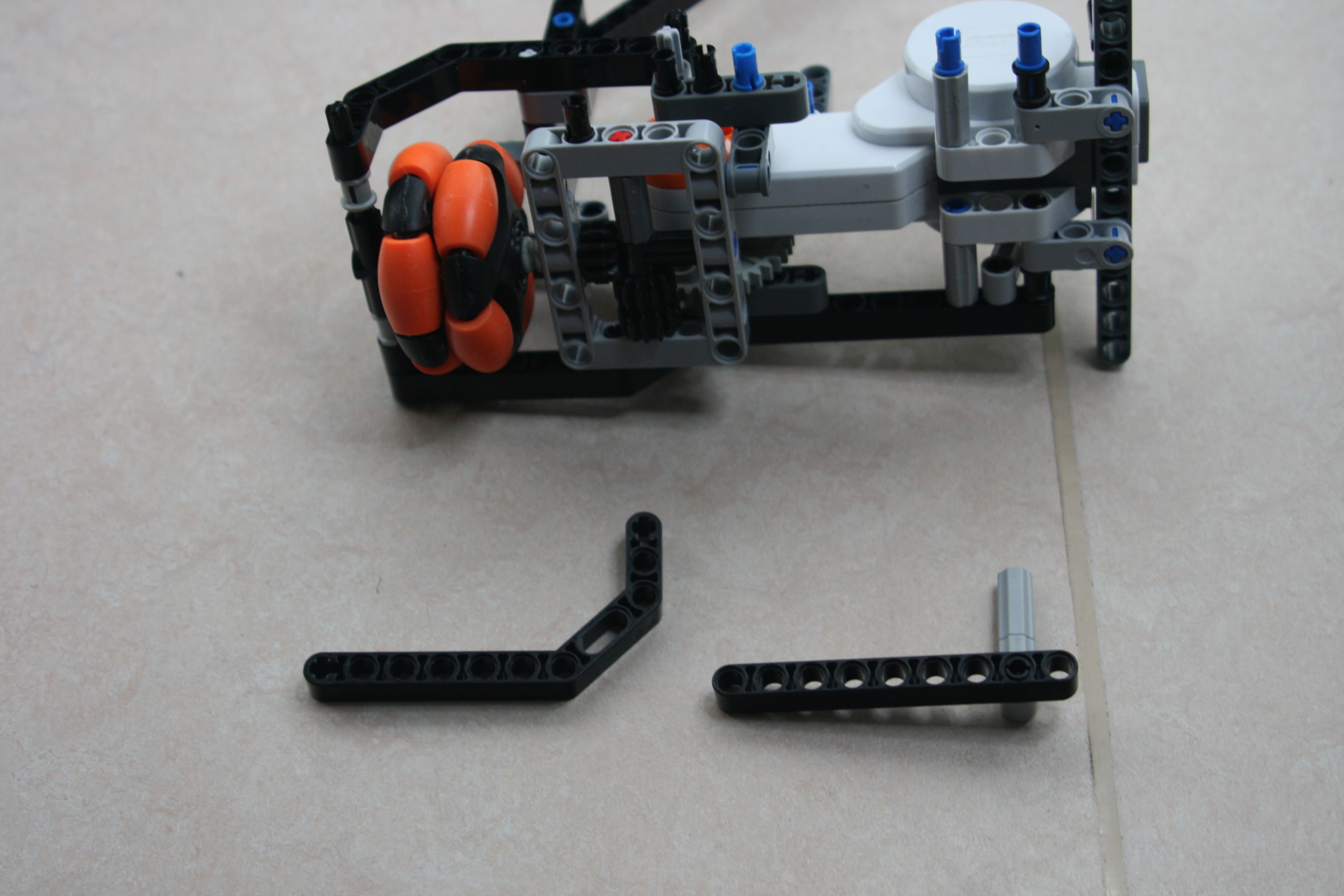
Here are the building instructions for the new leg.
If you only have two large EV3 motors you can easily modify the leg to use the EV3 medium motor. This motor can be attached directly to the drive axis of the wheel and to the underside of the frame. You will have no gearing. But as the medium motor rotates a bit faster you will still have plenty of speed in your robot.
One of the most fundamental problems in mobile robotics is to know the position of the robot. The question might seem simple, to get an answer is very difficult. There are two fundamentally different approaches to answer this question. The first approach uses dynamics to keep track of the robots position in respect to its starting position. Most often this technique uses wheel encoders to keep track of wheel movement. This is translated into a position of the robot. This is known as odometry. The second approach uses external references of which the location is known to calculate the position of the robot. Navigation based on stars is the oldest example of this technique, the GPS system is a recent example. As much as we come to rely on GPS nowadays, it is not very useful for our small indoor robots. Indoors the GPS signal is week and the error of a GPS position is in most cases bigger than the range of our robots.
I created a robot that uses the same principles as the GPS system is based on to localize itself. Instead of GPS satellites I use blinking LEDs (dLights from Dexter Industries) as beacons. The beacons are detected and identified using a standard NXT light sensor. Below you can see the robot in action. The robot is placed on a random location in a random direction in my room. It then has to find out where it is and then drive home.
The robot locates beacons by evaluating the variance in light level while scanning the horizon. Whenever a spot with large variation in light level is found, the robot stops to find out if this variation comes in a frequency that identifies one of the beacons. If so, the current heading of the robot is stored along with the identity of the beacon. If after a full scan three or more beacons are located then the robot has enough information to estimate its position. It does so by triangulation using a Snellius construction. Lejos software for the NXT has a class, lejos.robotics.localization.BeaconTriangle ,that implements all the difficult calculations. If more than tree beacons are located, the robot estimates its position by averaging the position estimated from all unique combinations three beacons. The result is an improved estimation.
I have built a new holonomic robot. It has a smaller wheelbase than Agilis and therefore turns faster. It has a 1:3 gear ratio, it’s maximum controllable speed is about 80 cm/second. It is also very sturdy thanks to all the triangles in its frame. And above all, I think it is prettier than Agilis. However, that is what every father says about his newborn. Below are some pictures


I got some feed-back on my last post with “building instructions” for Agilis. My friend Kirk wondered why I didn’t make proper instructions. He was not impressed by my lame excuses about odd angles or illegal builds and showed me things could be done. He was right, it was about time for me to master some Lego CAD tools. I choose to use LDraw and MLCad for the job. My fears for a steep learning curve proved wrong. The manual is quite good and I was up and running within an hour. The hardest thing to learn was the discipline to work precise immediately. One cannot build a sketch at first and then improve the model. Well, technically you can, but you shouldn’t as every brick you move triggers a chain of new moves that need to be made.

It was fun to create proper building instructions for Agilis. Along the way I also improved the gearbox as was suggested by another reader of my blog, Thimoty. You can freely download the instructions. I do appreciate constructive feedback. This is my first and I am sure there is room for improvement.
See this post for improved instructions!
By request I created building instructions for Agilis. Well, sort of. It is a series of photos made while taking one of Agilis legs apart. Presented to you in reverse order, so that it looks like a building instruction.
One warning before you start. The gear box can be assambled very easily, but it cannot be disassambled without some tools and, potentially, some damage.
The gear box displayed is for a 1:3.33 gear ratio. Here you find a picture of a 1:2 gear box. I think the 1:2 gear box is a better option.
The part list in the pictures 1 to 5 is for one leg only. Also I did not have the parts to make a nice color scheme so you might end up with a rainbow warrior in black and white if you follow my color scheme.
Please send me a message or picture when you built Agilis.


This time I introduce a new project: localization with a light sensor and light beacons. Localization, or navigation, is the art of determination of position and direction. The aim of the project is to determine the position and direction of a mobile robot with aid of a few beacons. Much like a sailor is able to determine the position of his ship with aid of a few lighthouses or known landmarks.

The beacons I use are dLight LEDs. Each beacon is blinking at a different rate, individual beacons can be recognized by it. Also lighthouses have a light characteristic to identify them by. The only difference between a light house and the beacons I use is in the blink rate, a lighthouse typically blinks once every couple of seconds, my beacons blink at a rate of 8 to 24 times a second.
The robot I use is the omniwheeled robot Agilis you might know from older posts. It can rotate on the spot and is equipped with a standard lego light sensor. I placed a tube in front of the light sensor to give it a narrow beam of detection. This makes it possible to localize the beacons with some accuracy. I also experimented with a lens to make it easier to detect faint light sources and to narrow down the angle of detection even further.
The localization process has three steps, localization of the beacons, identification of the beacons and calculating the robots position. The first two steps are done while the robot spins a full circle. The robot then tries to find as many beacons as possible. Once a beacon is found its location is determined and its identity established. After finishing the spin three beacons are selected and the robots location is calculated based on the relative angles between these beacons. I will discuss each of these steps in more detail over the next couple of posts starting with beacon localization in this post.
Beacons are located by Agilis while spinning on the spot. While spinning the robot keeps track of its direction by means of odometry based on the motor encoders. How this is done is explained in one of my older posts about Agilis. It uses a single standard light sensor to detect the beacons. Once a beacon is found its angle is determined and stored for later use. There are two problems in locating a beacon. The first one is to recognize a beacon reliably under various circumstances. Sometimes the beacons are the brightest objects on the horizon, at other times they are not. Therefore my attempts to find beacons by light intensity proved unreliable. Especially when a beacon was further away from the robot or when the sun was shining in my room. Only when I realized that the beacons were the only blinking objects in my room I managed to locate them reliably. I wrote an algorithm that calculated the amount of variation in the light level and I took this as an indicator of a beacon. The graph below shows the results of a 180 degrees scan. The dark blue line shows the light level measured by the light sensor during the scan. The peak on the left side of the scan is caused by a beacon, the peak on the right by a light bulb. The light blue line below shows the amount of variation in the light level. As you can see it does peak when scanning the beacon, but it does hardly raise when scanning the light bulb. The algorithm proved very successful in other (more complex) conditions too. For those interested, the algorithm takes a running average (using a low pass filter) of the absolute difference between two consecutive measurements.
![]() The second problem is to pinpoint the position of a beacon. This is both a physical problem, related to the sensor, as a logical problem, related to the algorithm used. The sensor has a rather wide beam of detection but is most sensitive to light sources right in front of it as the graph above shows. I narrowed the beam of detection by constructing a tube in front of the sensor with aid of technic connectors
The second problem is to pinpoint the position of a beacon. This is both a physical problem, related to the sensor, as a logical problem, related to the algorithm used. The sensor has a rather wide beam of detection but is most sensitive to light sources right in front of it as the graph above shows. I narrowed the beam of detection by constructing a tube in front of the sensor with aid of technic connectors  . I also tried a lens. Below is a graph made from a 360 degrees scan using a lens.
 ![]() I am not quite sure how I will narrow down the beam of detection in the final robot as there are drawback to each solution.
I am not quite sure how I will narrow down the beam of detection in the final robot as there are drawback to each solution.
The second issue with pinpointing the location of a beacon is in the logic. You cannot simply sort the samples and then take the three biggest values. In this case you will end up with three points from the biggest peak. So you need to find the biggest value
This time I will discuss the gyro sensor (again). What it measures. How to cope with offset and drift. And how to use it.
Gyro sensors are among the most widely used sensors in robots. They are often used in self balancing robots for keeping upright. They are also used in autonomous robots for keeping track of orientation. But also game controllers might use them to detect angular motion. A gyro sensor measures the angular velocity. In other words they measure how fast the sensor is rotating. This is most often expressed as degrees per second or radians per second. Some gyro sensors measure the angular velocity over one axis, others take measurements over two or three axes.
One should be aware that a rotating object always rotates over just one axis. This axis however can have any orientation. Compare this to speed. An object can move in just one direction at any given time. This direction however can be any direction in a three dimensional space. Most often we do express the speed of an object over three perpendicular axes. A landing plane might fly at a speed of 600 km/s and descent at a rate of 5 m/sec. Wind might blow it off course at a rate of 0.5 m/sec. But still this plane goes in one direction only. The same is true for angular velocity, an object rotates just with one speed, but we express its speed over three separate axes.
Let us take a look at the output of a typical gyro sensor. The graph below shows the output of a digital three axis gyro sensor (ITG-3200) over a period of 17 seconds. The X-axis is the time axis, the Y-axis shows the angular velocity expressed in degrees per second. After five seconds from the start of the measurement I rotated the gyro sensor clockwise for about 180 degrees. This took me about 3 seconds. After about 11.5 seconds I rotated the sensor back (counter clockwise).

This graph tells us quite a lot. First, we notice that the sensor is a three axis sensor. It returns three different signals at any given time. Second, we can see that the rotation I made took place of the third axis, this is the Z-axis. It means that I rotated the sensor in the XY-plane. This is true, I had the sensor flat on my desk and I rotated it while keeping it flat. Third, a clockwise rotation is expressed as a negative angular velocity and a counter-clockwise rotation as a positive angular velocity. This is a matter of convention and is called the right-handed orientation system. Fourth, we can see that when at rest the gyro signal is close to, but not exactly, zero. This is because the sensor is not perfect, it has a bit of an error. We’ll look into this error and ways to compensate for this later. And finaly, we cannot read the change of 180 degrees in orientation from the graph. This is because the sensor does not measure the orientation, instead it measures the angular velocity (speed of rotation). It is however possible to calculate the (change in) orientation from the angular velocity as I’ll explain later.
Let us concentrate on the error in the sensor signal right now. Below is a graph taken over a period of ten minutes while the sensor was at stand still all the time.
A perfect sensor would output a rate of velocity of zero for all three axes all the time. Obviously this sensor does not. The X-axis signal is around 2 instead of zero. This error is called the offset error. Every axis has its own offset error. For the X-asis this is around 2, for the Y-axis it is about 3.3 and for the Z-axis it is about -1.5. It is easy to correct for the offset error once you know how big it is. You just substract the offset error from the sensor signal to get a corrected value. The offset error itself can be calculated by taking the mean of a number of samples, take 100 for example.
The offset itself may seem constant, but in reality it is not. The offset of a sensor is influenced by several factors and can change over time as a result. This is called sensor drift. One of the biggest factors contributing to sensor drift is temperature. You can notice this when one starts using a sensor. When being used, the temperature of a sensor rises a bit. It gets hotter then the ambient temperature. As a result the offset of the sensor changes. If you need a very good signal you should take this into account and let the sensor warm up before calculating the offset.
Some gyro sensors, like the Hitechnic gyro for example, are seriously affected by changes in input voltage. As the NXT is battery powered this is a serious problem. Starting the motors of the NXT will result in a power drop and thus in a change in offset. There is a trick to avoid this if you have a sensor mux with an external power supply. Like this one from Mindsensors. In general I advise you to choose another gyro.
Even when temperature and power are constant the offset of a gyro will still vary a bit over time. This variation is called random walk.
There is a very elegant technique to deal with sensor drift. This is to constantly but slowly update the offset error of the sensor. Instead of treating the offset as a constant you treat it as a value that can change over time. To calculate the offset you now use the moving average of the most recent samples as the offset. Then you always have an up-to-date offset. Calculating the moving average however is CPU intensive and you also need a lot of memory to store the samples. Therefore it is better to use a low-pass filter instead of a moving average. This does not use extra memory and little computing power but the effect is the same.
This technique will work very well when the sensor is at stand still. But will it work well when it is rotating? Any rotation will influence the calculated offset. So of possible one should pause updating the offset while the sensor rotates? Sometimes another sensor can help to detect a rotation. A compass, an accelerometer or motor encounters can all be off help.
However, there is also another solution. This one is based on the notion that a rotation in one direction is very often compensated with a rotation in another direction. A balancing robot for example stays upright, so in the long term it does not rotate. It might lean forward and backward for short moments of time. But this forward and backward rotations cancel each other out on the long run. So in the long run the average signal of the sensor equals the offset of the sensor, even when there are rotations from time to time. This means that even under dynamic circumstances one can constantly update the sensor offset. One only has to make sure to use enough samples so that there is enough time for rotations to cancel each other out. This technique is useful for balancing robots where rotations are short. It is less useful for slow turning robots where rotations have a long duration.
There are situations where one needs to know the direction of the sensor. In navigation for example one needs to know in what direction a robot is heading. A gyro can provide this kind of information. There are some limitations though. So how do you transform angular velocity into direction? This is done by integration. This might seem difficult. But it really is not. If a robot rotates for 2 seconds at a speed of 90 degrees per second, it has rotated for 180 degrees. So integration is nothing more than time multiplied with speed. The graph below shows both the (offset corrected) angular velocity and the direction. During the test I rotated the sensor four times with 90 degrees clockwise, 360 degrees counter clockwise, 90 degrees counter clockwise and 90 degrees clockwise. After this the sensor was back at its start direction.
 The line representing the direction, labeled Rotation 2, clearly shows the steps of 90 degrees that I made. Careful examination of the data shows that according to the sensor the robot rotated with -358.8 degrees at max, where as I tried to rotate it with -360 degrees. This makes the sensor, and the integration, pretty accurate. However, after turning the sensor back to its start direction the calculated direction is not zero as is to be expected. Instead, it is about 5.7 degrees. This is not so good. What makes it even worse, there is no way to correct this. At least, not without the aid of another sensor of user intervantion. This is the main drawback of integration. Over time small errors (in the offset corrected) signal build up to become a large error in the integrated data.
But integration can be very useful nevertheless. Suppose a robot that needs to make exact turns. Using integration you can do so. But you need to reset the initial direction to zero just before making the term. This way the error in each turn will only be equal to the integration error that built up during this turn. This is small as making a turn does not last that long. In other words, you can make your individual turns accurate but not the overall direction of the robot.
But wait, there is one more thing. Integration only gives a change in direction. To know the real direction one should also know the direction before the changes took place. Quite often this initial direction can be assumed to be zero. But this is arbitrary and does not relate to the world. Although it might be all you need. If you need to relate the orientation of your sensor to the real world you need to align the sensor with the real world (make it point north) or you need another sensor that can do this for you. This could be a compass sensor.
I Proudly present my first Lego Technic sports car. My son and I built it together. It features a working 6 cylinder engine, moving bonnet, scissor doors, working steering, 2-tone interior and several body kits. Amongst the body kits is one that allows the car to fly!


Today I am proud to announce the winner of the dLight giveaway.
There were 30 participants. I want to thank them for their kind words about my blog. This positive feedback is really important to me and keeps me writing. I was also very pleased with the enthusiasm for the dLights in the reactions. Most people said the dLights were cool. I hope we’ll see some nice applications of the dLights in the future.
The winner of this contest was drawn by my son from a basket containing 30 small papers, each with the name of one of the participants. And the winner is Leon Overweel! Congratulations Leon!
Leon is a talented NXT builder and you might know him from his website World of Mindstorms. I am curious to see what creative uses he’ll come up with.
